STAGE 3

Algorithms to improve the efficiency of the UGV propeller’s kinematics when moving on rough terrain

Analysis of the energy efficiency of propulsion solutions during movement

A methodology is presented that boils down to the development of an algorithm for developing models for simulating UGV dynamics, followed by a presentation of the results obtained through simulation of a UGV’s movement when driving in a straight line or taking a turn, with the purpose of analyzing the energy efficiency of different propulsion solutions. Proposed simulation models are developed in the Matlab programming environment, using predefined blocks from the libraries of Simulink, Simscape Driveline, Simscape Electrical and Simscape Multibody subroutines. Based on the ATM model UGV, models are built that simulate the power supply and operation of DC motors, the command and control of the motors through control drivers, the operation of the gearboxes in the motor structure, as well as the interaction between the track, wheels and chassis of the ATM model UGV.
The modeling diagram proposed for the simulation of the DC motor operation, allows retrieval and visualization of the signals resulting from the simulation process (torque, speed, power, absorbed current, supply voltage). Comparing the values obtained by simulating the individual operation of the motor with the values specified by the manufacturer, it appears that the proposed model is able to approximate the motor operation in good conditions. This is based on the fact that when simulating both the operation with the output shaft locked and when idling, we obtained values for speed and moment close to those obtained experimentally by the manufacturer.

The proposed model for simulating the operation  of the power supply, command and control system of DC motors is developed using logic programming elements from the Simulink library, as well as elements from the Simscape Electrical library. These elements are capable of simulating the components of the command and control driver or those that allow energizing the electrical consumers that make up the UGV (DC motor, sensors and Arduino board). The interconnection of these components together with the modeling diagram of the signals required to drive the motor, results in the simulation of the driver that allows the command and control of the DC motor.

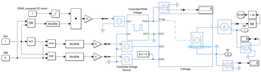
The command and control driver used in the construction of the UGV has an H-type bridge in its structure, which, depending on the signal received from the microcontroller (Arduino board) on pins (INA) or (INB), commands the braking of the motor through rotation of the output shaft clockwise or anticlockwise as shown in the control chart. The motor load is controlled with the pin (PWM) by introducing a signal with values in the range (0, 1), where zero represents zero load (low) and one (high) maximum load. When forward motion is simulated (INA = 1, INB = 0, PWM = 1), a positive 6V voltage is supplied to the DC motor through the (M+) port. When reverse motion is simulated (INA = 0, INB = 1, PWM = 1), a voltage of -6V is supplied to the motor and when braking is simulated (INA = 1, INB = 1, PWM = 1), a voltage of 0V is supplied to the motor.
The modeling diagrams of the interaction between the ground and the UGVs wheels, and the one between the drive wheels and the body of the UGV, are developed, both in the Simscape/Driveline and in the Simscape/Multibody simulation environment.
The simulation diagrams specific to the main systems of the UGV are connected to each other with the help of Simscape connecting elements, thus allowing the transfer of energy between the mechanical components of the UGV. The interconnection of the proposed modeling diagrams for the UGV component subsystems results in the UGV dynamics simulation model, capable of simulating the forward or backward rectilinear movement of the UGV, as well as the cornering movement of the UGV forward or backward.

The simulation of the rectilinear movement of the UGV reveals a graphical time dependence for:

  • UGV speed and trajectory in the start-up process;
  • torques loading the output shaft of the DC motor, the output shaft of the gearbox and the drive wheel;
  • traction forces from the wheels of the UGV;
  • forces loading the wheels of the UGV in vertical direction;
  • wheel slip in longitudinal and transverse directions;
  • power consumed during the start-up process;
  • specific speeds of the motor output shafts, gearbox output shafts and drive wheels;
  • roll, pitch and yaw movements of the UGV;
  • UGV displacement along the three axes of the reference system (x, y, z).

The simulation of the cornering movement of the UGV reveals a graphical time dependence for:

  • UGV speed and trajectory during the start-up process;
  • speeds and trajectories of the UGV wheels during the start-up process;
  • power consumed during the start-up process;
  • torques loading the output shaft of the DC motor, the output shaft of the gearbox and the drive wheel;
  • traction forces from the wheels of the UGV;
  • forces loading the wheels of the UGV in vertical direction;
  • wheel slip in longitudinal and transverse directions;
  • UGV displacement along the three axes of the reference system (x, y, z).